cWhat Is IO-Link?
Nowadays, we hear a catchphrase more frequently, "Industry 4.0." Industry 4.0 refers to super-fast, fault-free manufacturing, implemented via automation, precise computer-controlled robots, intelligent machines, smart technologies, and most importantly, real-time access of information through Internet of Things (IoT) technologies and massive data processing (Big Data/Cloud). A vast transformation has occurred in industrial manufacturing in the past few decades with the rapid development of automation and related technologies. In intelligent factories where machines and sensors are connected to the networks, devices communicate with each other, and computers monitor the whole network of the system. The basic idea is to capture the real-time data from all the components of the manufacturing chain and remotely access data anywhere in the factory to minimize downtime caused by faults along with the comprehensive, real-time diagnostics.
The backbone of today's smart factory of Industry 4.0 is the IO-Link. IO-Link is a standardized, point-to-point serial communication link for data exchange between two nodes. One endpoint of a link is typically a sensor including pressure, temperature, proximity, position, and force sensors, or an actuator such as hydraulic cylinders, linear actuators, and pneumatic control valves, among others. Such devices are normally referred to as an IO-Link device. The other endpoint of the link is a IO-Link master. The IO-Link master usually has 4 to 8 ports, and each port establishes a bidirectional communication with one IO-Link device. The IO-Link master receives all the data from the devices and transmits that information to a PLC or an industrial computer via a standard Fieldbus or industrial Ethernet. The complete IO-Link system architecture is shown in Figure 1.
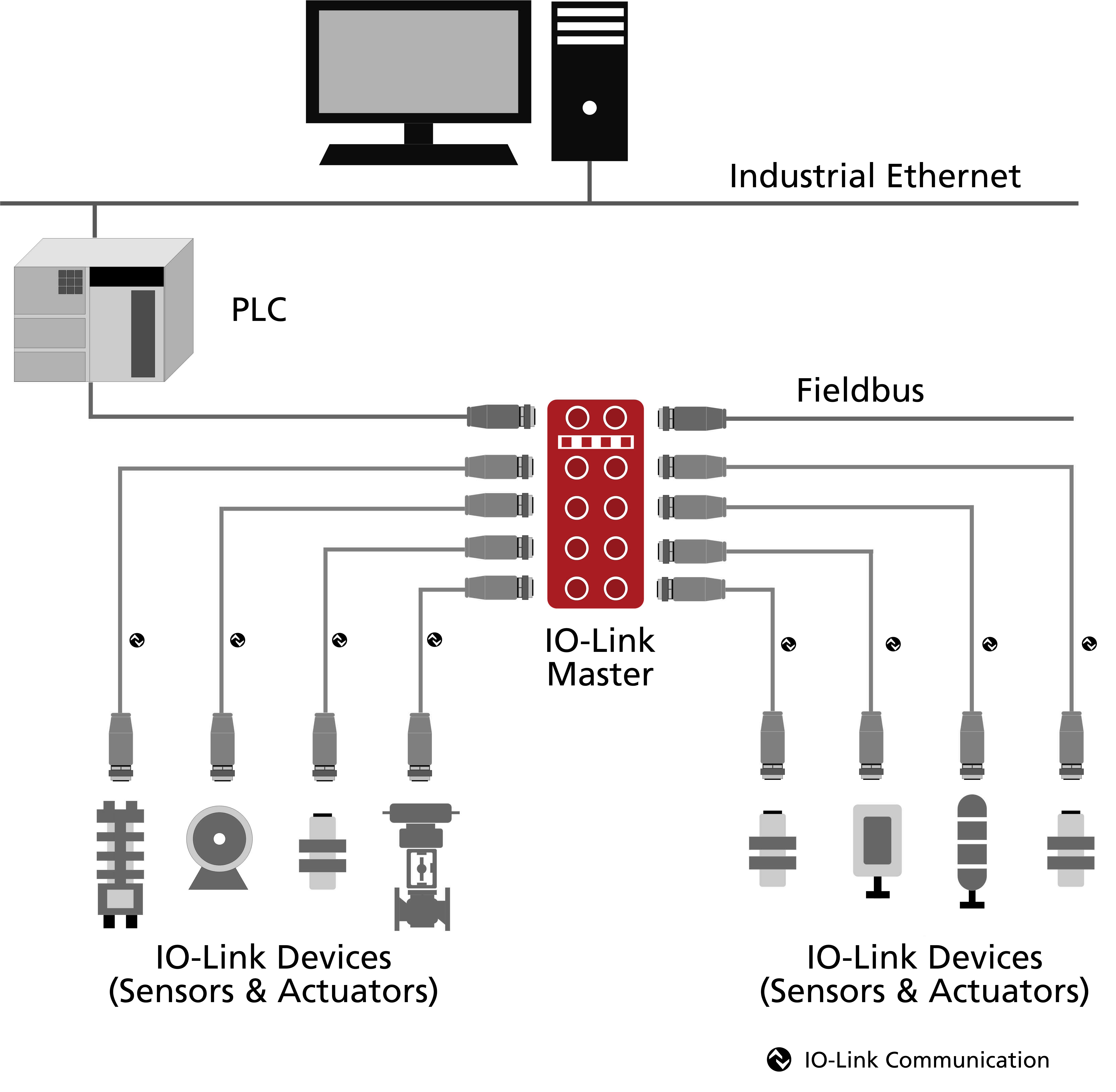 Figure 1. IO-Link system architecture
EOS/ESD Protection of the IO-Link Devices
IO-Link has made the whole industrial manufacturing process stress-free and fault-free. The integrated circuits used in IO-Link transceivers work in a harsh manufacturing environment. Not only that, the IO-Link devices can be plugged in and unplugged from the IO-Link masters when required. These working conditions can cause transient voltage spikes like electrostatic discharge (ESD) events that can reach thousands of volts, potentially damaging the transceivers. Traditionally, transient voltage suppression (TVS) diodes protect IO-Link ports and transceivers from ESD threats by arresting the system-level ESD peak, thereby diverting high currents away from the port. Before going into the protection details, let us first talk about the IO-link ports.
The IO-Link devices use standard 3-wire or 4-wire connecting ports (M12 ports) called Type-A or Type B ports. The cable between the IO-Link master and the IO-Link devices can be up to 20 meters long. The pin configuration of the ports is shown in Figure 2.
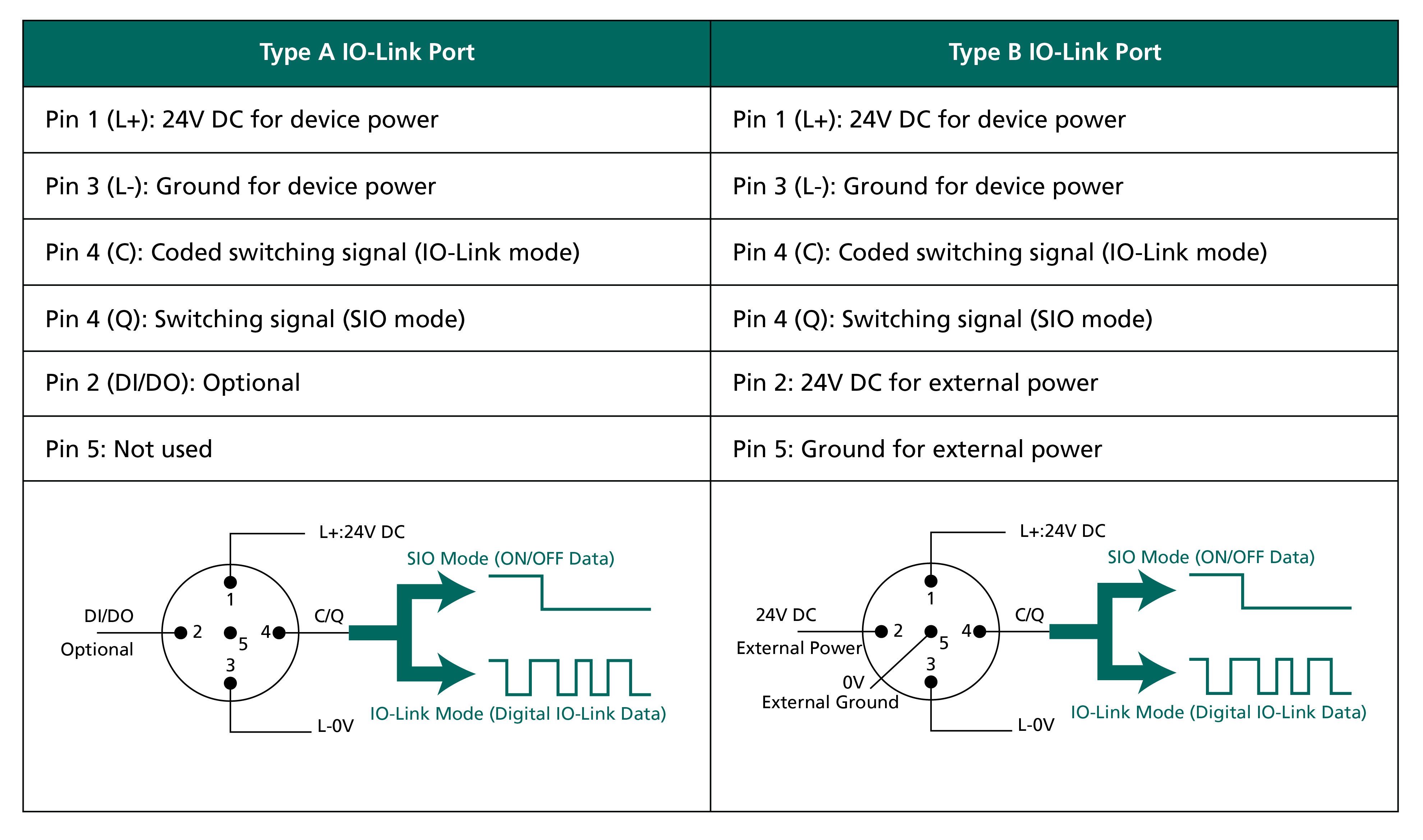 Figure 2. Type A and Type B IO-Link Ports
In both the ports, 24V DC is provided at pin 1 to power the IO-Link devices. Pin 4, denoted as C/Q, carries the communication or signal information. C is used for single-drop digital communication interface (SDCI) or IO-Link mode, where the communication is bidirectional with digital inputs (DI) or digital outputs (DO). In IO-Link mode, bidirectional communication with transmission rates of 4.8kBit/s (COM1), 38.4kBit/s (COM2), and 230.4kBit/s (COM3) are possible. Q is used for standard input-output (SIO) communication. Pin 2 is optional for Type A and sometimes set by the manufacturers to connect an additional digital input or digital output signal. Otherwise, it remains not connected (NC). Pin 5 remains not connected in the Type-A port as well. The Type B port is used for IO-Link devices, requiring additional power from an independent 24V power supply. The separate power supply is connected between Pin 2 and Pin 5. Some more extensive devices, such as valve banks and other actuators, utilize an additional power supply via Pin 2 and Pin 5.
During a transient event, these four pins of the IO-Link port should endure both positive and negative polarity surges. A careful surge protection testing is required between any of the two pins of the connector. Also, the standards like IEC 61000-4-2 for ESD, IEC 61000-4-4 for burst/EFT, and IEC 61000-4-5 for surge requirements should be met while protecting the circuit. Most importantly, a compact solution is beneficial to save real estate. Circuit protection devices can be selected considering 15% of input supply tolerance. On top of that, we can consider a little more coverage. So for a 24V application like the IO-Link, a 33V protection device is suitable.
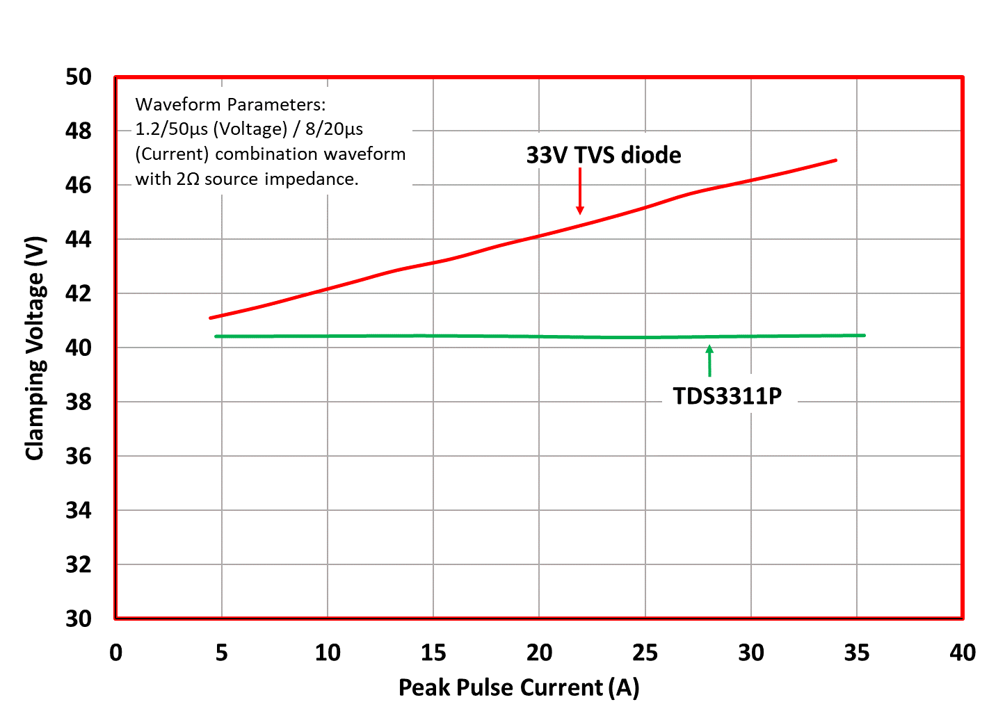 Figure 3. Clamping voltage versus Peak Pulse Current comparison
Semtech offers a wide range of protection devices for IO-Link devices and masters transceivers. The new TDS3311P SurgeSwitch™ from Semtech's SClamp® system protection portfolio is ideally suited to safeguard the IO-Link devices and masters. SurgeSwitch does not use a conventional PN junction TVS diode for protection. Instead, it uses a surge-rated field-effect transistor (FET) as the primary protection element, which is used as a voltage-controlled switch. This technology brings substantial advantages in protecting IO-links from ESD and EOS events. One advantage worth mentioning here is the nearly constant clamping voltage across the rated peak pulse current range, as shown in Figure 3. The clamping remains stable over the operating temperature range; it does not degrade over temperature like conventional TVS diodes. Consistent performance over temperature is a critical point in selecting a protection device for an IO-Link circuit working in a rugged industrial environment. Another significant advantage is that the clamping voltage of TDS3311P is at least 30% less than the conventional TVS ESD protection devices (Figure 4).
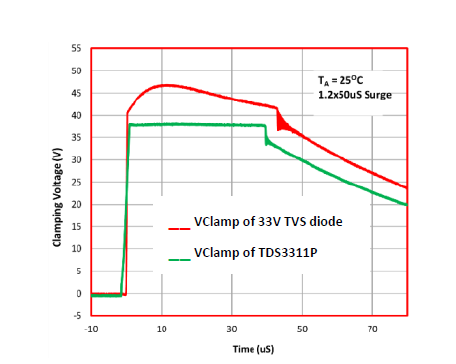 Figure 4. Lower clamping voltage of TDS3311P
Semtech's TDS3311P is specifically designed to protect the voltage bus or data line with an operating voltage of 33V. It is rated for a high energy peak pulse current capability up to 35A (tP=8/20µs per IEC 61000-4-5). TDS3311P can be used to meet the common industrial voltage surge standard of ±1kV (RS=42Ω, CS=0.5F). It protects one IO-Link line with a minimum breakdown voltage of 36V. The maximum clamping voltage is 42V at Ipp=35A. TDS3311P provides the transient protection as per the specification in IEC 61000-4-2 (ESD) at ±30kV (Air), ±30kV (Contact). It has a dynamic resistance of only 0.20Ω (Typical). TDS3311P is available in a 6-lead DFN package with a nominal dimension of 1.6 x 1.6 x 0.55 mm.
Now let us look into a few examples of protecting the IO-Link ports. The ESD protection of 3 pins IO-Link port can be done as shown in Figure 5. TDS3311P is used as an ESD protection device from D1 to D3. For reverse polarity protection on the VBUS line, a TVS diode µClamp™3671P is recommended to use. Two TDS3311P facing each other can be used for bidirectional protection. Figure 6 shows the ESD protection options of the IO-Link 4 pin port.
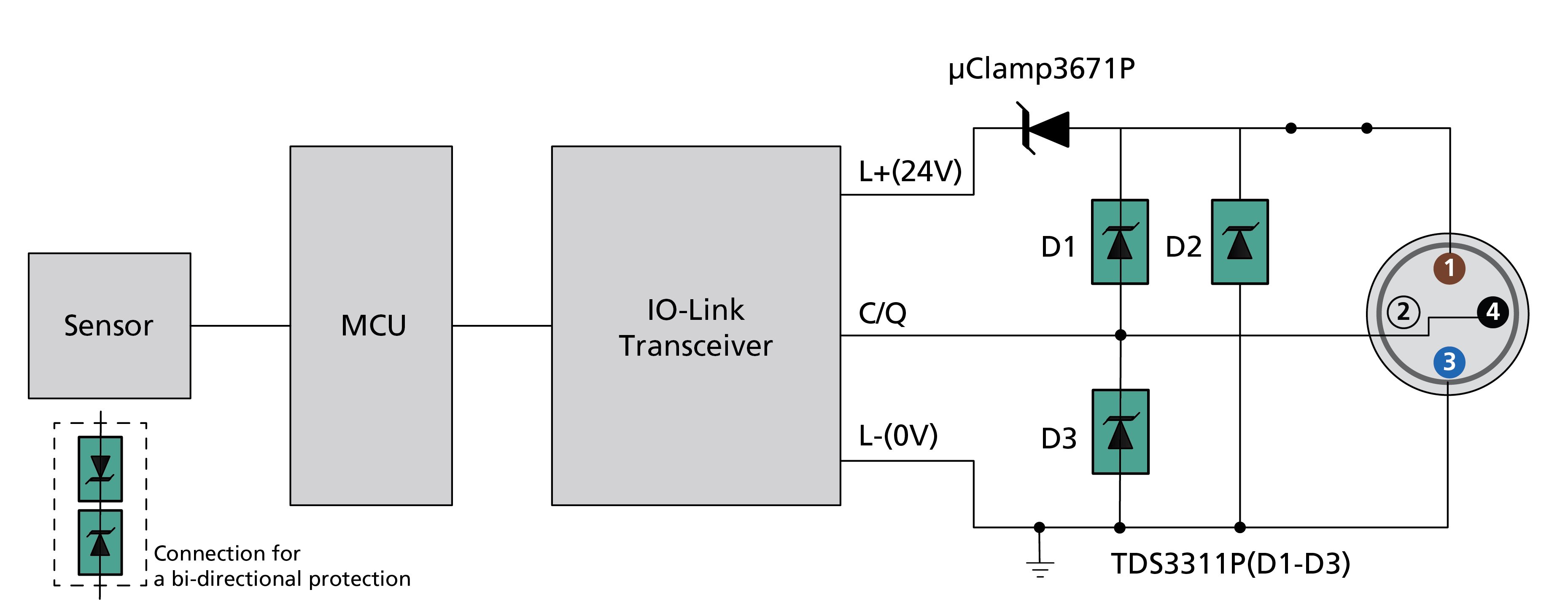 Figure 5. ESD protection of IO-Link device three-pin port
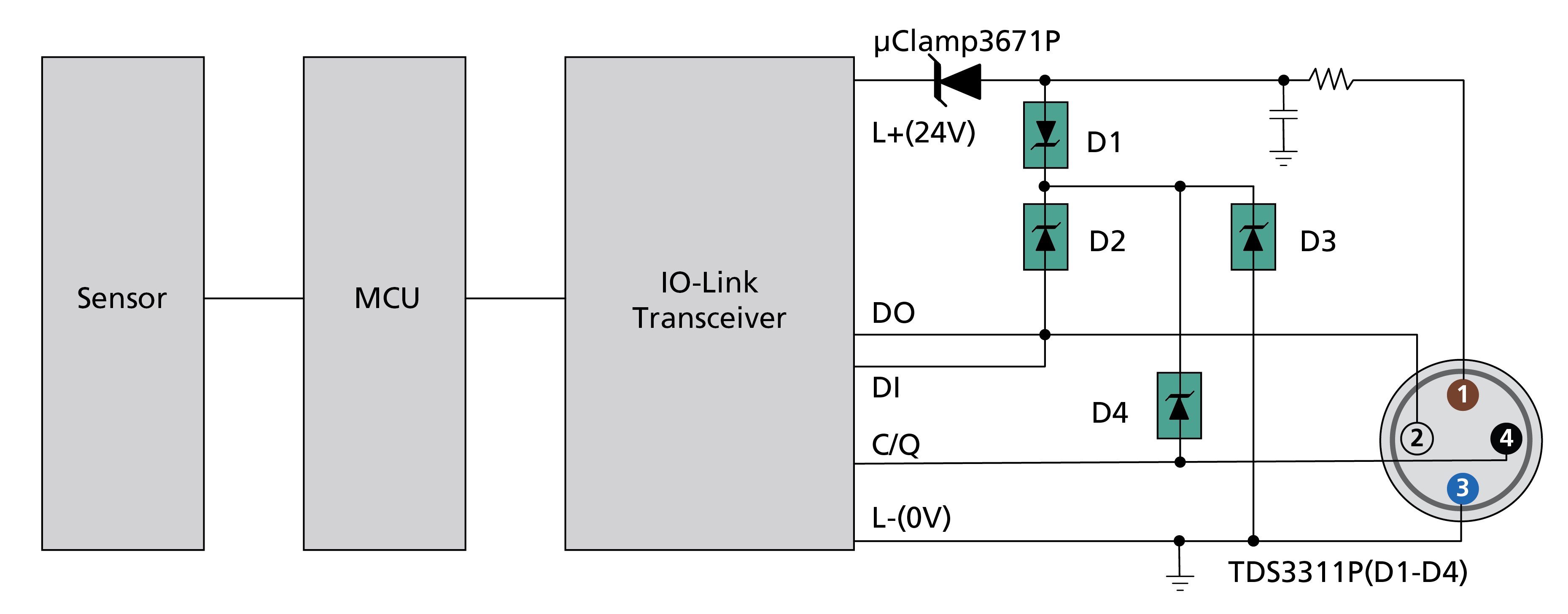 Figure 6. ESD protection of IO-Link device four-pin port
Similar to IO-Link devices, IO-Link master transceivers also need ESD protection. Each IO-Link master consists of 4 to 8 ports, provides point-to-point communications between IO-Link devices, and serves as a gateway to the PLC and the Fieldbus. Usually, quad transceivers are used for the connection of 4 ports. The master ports initiate communication and exchange data to and from the devices. Master ports need protection devices to meet standards like IEC 61000-4-2 for ESD immunity, IEC 61000-4-4 for burst/EFT immunity, and IEC 61000-4-5 for surge immunity. Semtech's TDS3311P can protect the master ports during transient events, as shown in Figure 7.
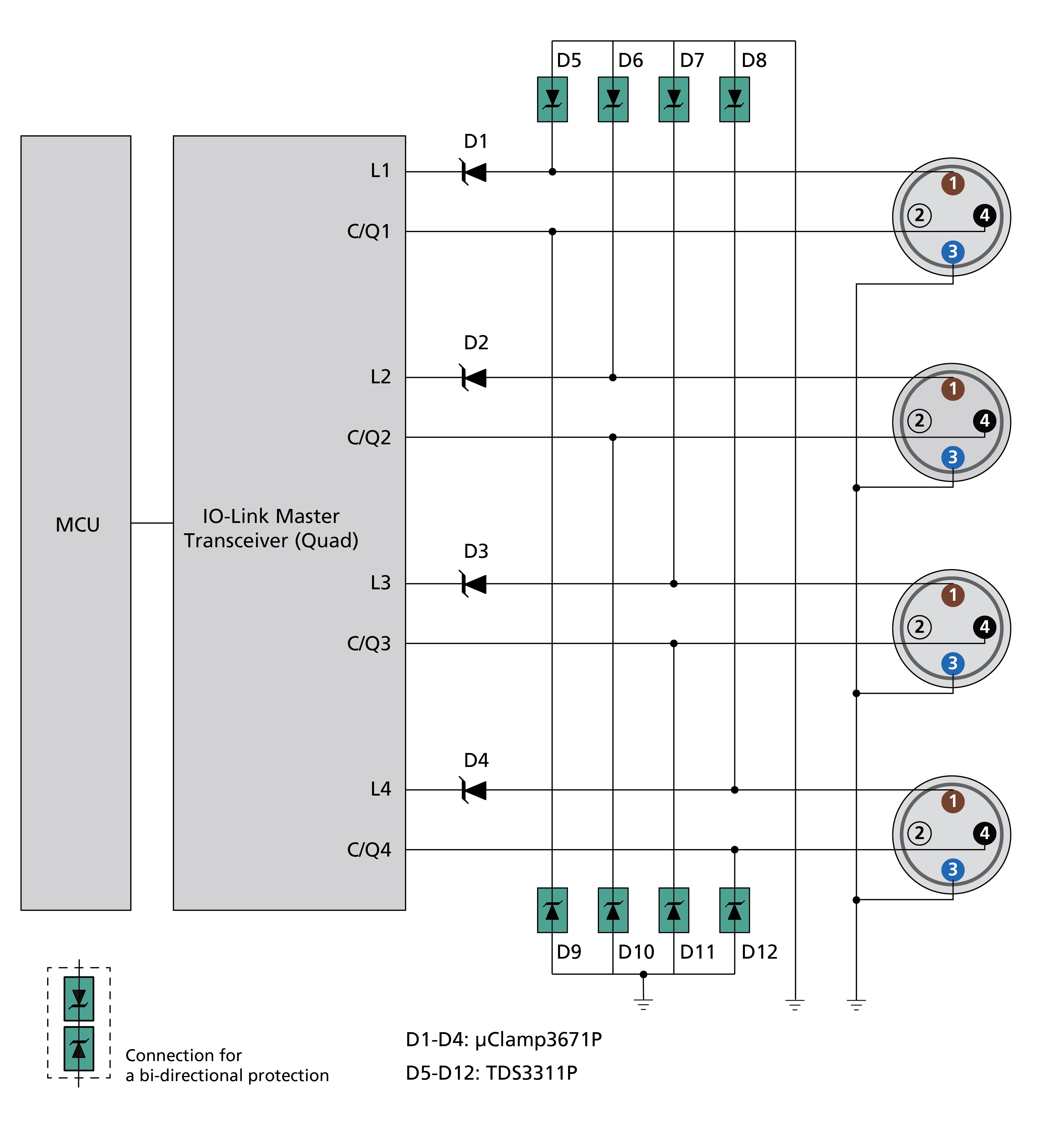 Figure 7. ESD protection of IO-Link Master
Semtech also offers traditional TVS diodes for IO-Link ESD and surge protection. The table below shows some conventional Semtech parts used for multi-line protection and higher voltages applications.
| Part Name | Description | VRWM | IEC ESD (Air/Contact) | Surge (8x20µs) |
CL(Typ) |
Package |
| µClamp3612S | 2-Line Uni, 1-Line Bi | 33V | ±30kV/±30kV | 16A | 53pF for line-line; 108pF for line-gnd | SOT23 |
| SDC36C* | 2-Line Uni, 1-Line Bi | 33V | ±15kV/±8kV | 4A | 100pF | SOT23 |
| µClamp3673P | 3-Lines Uni | 36V | ±30kV/±30kV | 18A | 25pF | DFN 3.0x1.6x0.57mm |
| µClamp3603T* | 3-Lines Uni | 36V | ±20kV/±15kV | 3.5A | 25pF | DFN 1.7x1.0x.0.4mm |
| µClamp3671P | 36V | ±30kV/±30kV | 18A | 150pF | DFN 1.5x1.0x0.5mm |
* The TVS of SDC36C and µClamp3603T for IO-Link protection can be found in the Maxim reference design of MAX14820 & MAX14827A.
Conclusion
IO-Link is an integral part of the fourth industrial revolution (Industry 4.0) and is immensely popular due to its simplicity of use. The usage model of IO-Link ports are exposed to substantial ESD spikes. The ports must be safeguarded from the dangers of ESD threats so that the industrial manufacturing chain remains fault-free. Semtech's wide range of trusted TVS products have long been the preferred method for shielding many of the world's IO-link devices. With the introduction of Semtech's SurgeSwitch devices, significantly elevated ESD protection is now possible to ensure even more dependable performance of IO-Link communication in harsh industrial environments. Semtech's SurgeSwitch TDS3311P is ideal for safeguarding IO-Link ports – enabling a smooth, glitch-free uninterrupted user experience.

Semtech®, the Semtech logo, and SClamp® are registered trademarks or service marks, and SurgeSwitch™ and µClamp™ are trademarks or service marks of Semtech Corporation or its affiliates.